| System Software |
| OS |
Windows CE 5.0 |
| .NET Compact Framework |
2.0 |
| Embedded Service |
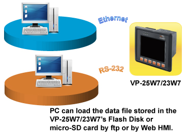
FTP Server, Web Server |
| Development Software |
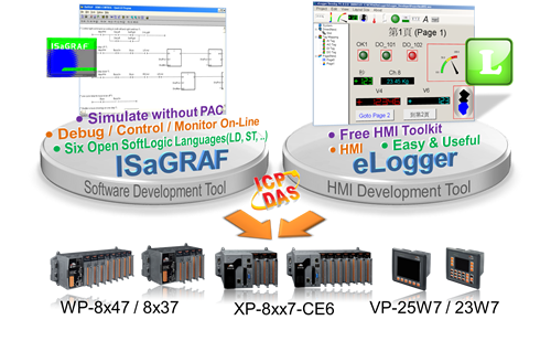
| ISaGRAF Software |
ISaGRAF Version 3 : IEC 61131-3 standard. Languages: LD, ST, FBD, SFC, IL & FC |
| Max. Code Size |
Accepts max. 1 MB ISaGRAF code size (Appli.x8m must < 1 MB) |
| Non-ISaGRAF |
Options: Microsoft EVC++4.0 or VS .NET 2003/2005/2008 (VB .NET 2003/2005/2008, C# .NET 2003/2005/2008) |
| Web Service |
| Web HMI |
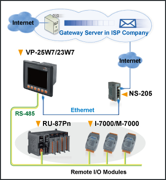
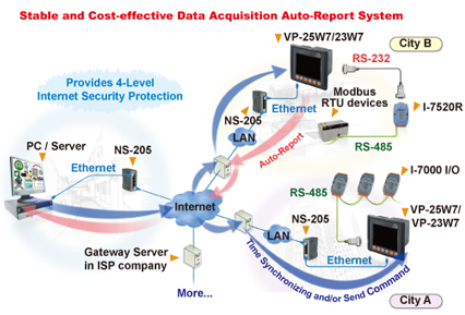
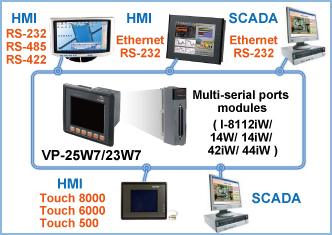
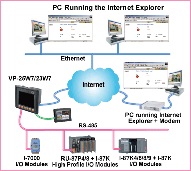
Supports Web HMI function, PC running Internet Explorer can access VP-2xW7 via Local Ethernet or Internet or dial Modem, monitoring and control. |
| Security |
Web HMI supports three levels user name and password protection |
| Power Supply |
| Input Range |
+10 ~ +30 VDC (unregulated) |
| Isolated |
1 kV |
| Capacity |
2.5 A, 5 V supply to I/O expansion slots |
| Consumption |
7.2W (0.3A @ 24VDC) |
| General Environment |
| Temperature |
Operating: -20°C ~ +70°C ,
Storage : -30°C ~ +80°C |
| Humidity |
5 ~ 95 % RH (non-condensing ) |
| System |
| CPU |
CPU: PXA270, 32-bit and 520 MHz or compatible |
| Dual Watchdog Timers |
Yes |
| RTC (Real Time Clock) |
Provide seconds, minutes, hours, day of week/month, month and year, valid from 1980 to 2079 |
| SDRAM |
128 MB |
| Dual Battery Backup SRAM |
512 KB (for 5 years data retention while power off) |
| FLASH |
96 MB (64 MB for OS image, 31 MB for built-in Flash disk, 1 MB for registry) |
| Expansion Flash Memory |
microSD socket with 1 GB microSD card (can support up to 16 GB compatible microSDHC card) |
| EEPROM |
16 KB, Data retention: 40 years. 1,000,000 erase/write cycles |
| Rotary Switch |
Yes (0~9) |
| NET ID |
From 1 ~ 255, User-assigned by software |
| Serial Number |
Yes,64-bit hardware unique serial number |
| Serial Ports |
| First Ethernet |
RJ-45 x 1, 10/100 Base-TX (Auto-negotiating, Auto MDI/MDI-X, LED indicators)
Please use NS-205/NS-208 Industrial Ethernet Switch. |
| Second Ethernet |
The default VP-25W7/VP-23W7 has only one Ethernet port. They can add one optional I-8135W card in its slot 0 ~ 2 to expands the second Ethernet port. |
| USB Port |
one USB 1.1 Host ports for USB mouse, keyboard or USB drive |
| COM0 |
Internal communication with the I-87K High Profile modules in slots |
| COM2 |
RS-485 (D2+, D2- ; self-tuner ASIC inside); Speed: 115200 bps max. ; 2500 VDC isolated |
| COM3 |
RS-232 (RxD, TxD, CTS, RTS, DSR, DTR, CD, RI and GND);
Non-Isolated; Speed: 115200 bps max. |
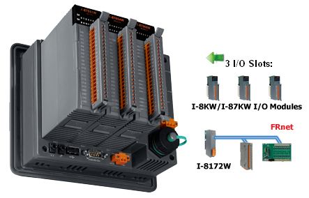
| I/O Slots |
| Slot Number |
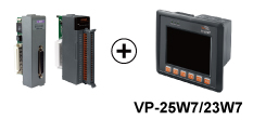
VP-25W7/VP-23W7: 3 slots (slot 0 ~ slot 2) |
| Accept only High Profile I-8K Parallel & High Profile I-87K Serial I/O boards |
| Hot Swap (will be available) |
For High Profile I-87K I/O modules in slot 0 to slot 2 only |
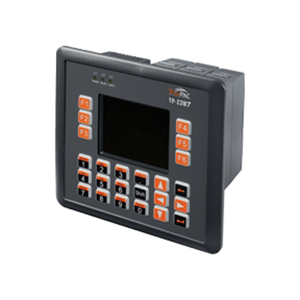
| MMI (Man Machine Interface) |
| LCD Monitor |
3.5” TFT (Resolution 320 x 240) |
5.7” TFT (Resolution 640 x 480) |
| Touch Panel |
- |
Yes |
| Rubber Keypad |
24 keys |
6 keys |
| Audio |
Microphone-In and Earphone-Out |
| LED Indicators |
3 Dual-Color LEDs (PWR, RUN, LAN1, L1, L2, L3; L1~L3 For User Programmable) |
| Dimensions (W x L x H) |
182 mm x 158 mm x 125 mm |
| Ingress Protection |
Front panel: IP65 |
| Motion |
| Motion Control |
One I-8091W (2-axis) or two I-8091W (4-axis) can do motion control, only one I-8091W can do X-Y dependent motion. |
| PWM Output |
| High Speed PWM Module |
I-8088W, 8-ch PWM outputs, 10Hz ~ 500 KHz (non-continuous), duty: 0.1 ~ 99.9% |
| DO Module as PWM |
8-ch. max. 250 Hz max. For Off=2 & On=2 ms . Output square curve: Off: 2 ~ 32766 ms, On: 2 ~ 32766 ms. Optional DO Boards: I-8037W, 8041W, 8041AW, 8042W, 8050W, 8054W, 8055W, 8056W, 8057W, 8060W, 8063W, 8064W, 8068W, 8069W (Relay Output boards cannot generate fast square pulse) |
| Counter, Encoder, Frequency |
| Parallel DI Counter |
8-ch. max. For 1 controller. Counter val: 32-bit. 250 Hz max. Min. ON & OFF width must > 2 ms. Optional DI boards:
I-8040W, 8040PW, 8042W, 8048W, 8050W, 8051W, 8052W, 8053W, 8053PW, 8054W, 8055W, 8058W, 8063W. |
| Serial DI Counter |
Counter input: 100 Hz max. Counter value: 0 ~ 65535 (16-bit)
Optional serial I-87K DI boards: I-87040W, 87046W, 87051W, 87052W, 87053W, 87053W-A5, 87054W, 87055W, 87058W, 87059W, 87063W. |
| Remote DI Counter |
All remote I-7000 & I-87K DI modules support counters. 100 Hz max. value: 0 ~ 65535 |
| High Speed Counter |
I-8084W : 250 kHz max. 32 bit; I-87082W: 100 kHz max. 32 bit; I-87088W : 500 kHz max. 32 bit |
| Encoder |
I-8084W: 250 kHz max. , 4-ch encoder, can be dir/pulse, or up/down or A/B phase (Quard. mode)
* Not support Encoder Z-index |
| Frequency |
I-87082W: 2-ch, 1 Hz ~ 100 kHz; I-87088W: 8-ch, 0.1 Hz ~ 500 kHz; I-8084W: 8-ch, 1 Hz ~ 250 kHz; |
| Protocols |
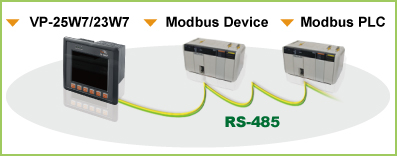
Modbus RTU/ASCII Master
(multi-port) |
Up to 10 COM Ports (COM2~ 3 and COM5~COM14 if multi-serial port boards are plugged in) can support multi-ports of Modbus RTU/ASCII Master protocol to connect to other Modbus Slave devices. |
| Modbus RTU Slave Protocol |
Up to 5 COM Ports (one of COM2/3 and COM5 ~ COM8) can support Modbus RTU Slave protocol for connecting ISaGRAF, PC/HMI/OPC Server & HMI panels. |
| Modbus TCP/IP Slave Protocol |
Ethernet Ports all support Modbus TCP/IP Slave protocol for connecting ISaGRAF & PC/HMI. LAN1 and optional 2nd Ethernet Port in I-8135W support total up to 32 connections. When one Ethernet port is broken, the other one can still connect to PC/HMI. |
| Web HMI Protocol |
Ethernet ports for connecting PC running Internet Explorer. |
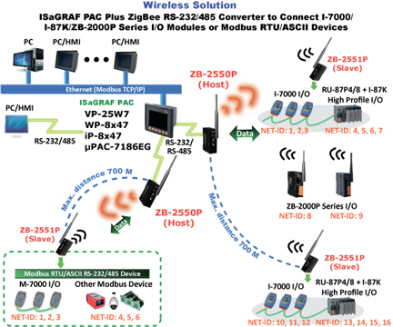
I-7000 & I-87K RS-485
Remote I/O |
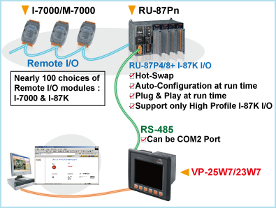
One of COM2, COM3 supports I-7000 I/O modules, I-87K base + I-87K Serial I/O boards and RU-87P1/2/4/8 + I-87K High Profile I/O boards as Remote I/O. Max. 255 pcs. of I-7000/87K Remote I/O modules for one controller. |
| M-7000 Series Modbus I/O |
Max. 10 RS-485 ports (COM2~3 & COM5~COM14 if multi-serial port boards are plugged in) can support M-7000 series Modbus I/O. Each port can connect up to 32 M-7000 Modules. (with optional I-7510 repeater connected can connect up to more than 32 M-7000 Modules) |
| Modbus TCP/IP I/O |
Supports ICP DAS Ethernet I/O. If LAN1 is broken, it will switch to the 2nd Ethernet port (in optional I-8135W card) automatically to continuously work. (This need LAN1 & the 2nd Ethernet’s IP are set in the same IP domain) |
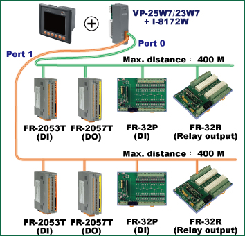
| FRnet I/O |
Support max 3 pcs. I-8172W boards in slot 0 to 2 to connect to FRnet I/O modules, like FR-2053, FR-2057 FR-32R, FR-32P, atwww.icpdas.com > FAQ > Software > ISaGRAF Ver.3 (English) FAQ-048. Each I-8172w board can connect up to 256 DI plus 256 DO channels. |
| Send Email |
Supports mail_snd and mail_set functions to send email with one attached file via Ethernet port. |
| Ebus |
To exchange data between ICP DAS’s ISaGRAF Ethernet controllers via Ethernet port. (LAN1 Port only) |
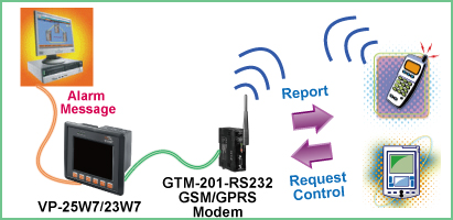
| SMS: Short Message Service |
One of COM3 (or COM5 if multi-serial port board is plugged in) can link to a GSM Modem to support SMS. User can request data/control the controller by cellular phone. The controller can also send data & alarms to user’s cellular phone. Optional GSM Modems: GTM-201-RS232 (850/900/1800/1900 GSM/GPRS External Modem) |
| User-defined Protocol |
User can write his own protocol applied at COM2~COM3 & COM5~COM14(if multi-serial port boards are plugged in) by Serial communication function blocks. |
| Modem_Link |
No support Modem_Link. |
| MMICON/LCD |
COM3 or COM5(if I-8112W/8114W is found) supports ICP DAS's MMICON. The MMICON is featured with a 240 x 64 dot LCD & a 4 x 4 Keyboard to display picture, string, integer, float, & input a char, string, integer & float. |
UDP Server & UDP Client
(Exchange Message &
Auto-Report) |
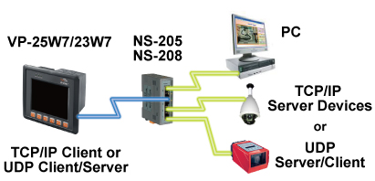
LAN1 or 2nd Ethernet port (in optional I-8135W card) support UDP Server and UDP/IP Client protocol to send/receive message to/from PC/HMI or other devices. For example, to automatically report data to InduSoft's RXTX driver. |
TCP Client
(Exchange Message &
Auto-Report) |
LAN1 or 2nd Ethernet port (in optional I-8135W card) support TCP Client protocol to send/receive message to/from PC/HMI or other devices which support TCP Server protocol. For example, to automatically report data to InduSoft ‘s RXTX driver, or to connect a location camera. |
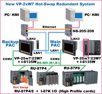
| New Hot-Swap and Redundant System |
Must enable the 2nd Ethernet port in the optional I-8135W card. This redundant system has setup two “Active IP” address point to the active VP-25W7/VP-23W7 's LAN1 and 2nd Ethernet ports always. One or two or more PC / HMI / SCADA can communicate with this redundant system via one of the two given active IP. So the PC / HMI / SCADA can access to the system easily without any notice about which VP-25W7/VP-23W7 is currently active. Moreover, the new redundant system can integrate with the RU-87P4 and RU-87P8 expansion unit plus the I-87K high-profile I/O cards to support the hot-swap application. If the I/O card is damaged, the maintenance person just takes one good-card with same model number to hot-swap the damaged one without stopping this redundant system. Please refer to www.icpdas.com > FAQ > Software > ISaGRAF Ver.3 (English) FAQ-093. |
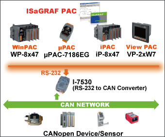
| CAN/CANopen |
VP-25W7/VP-23W7 can use its COM3 or COM5~COM14 resides at the I-8112iW/8114W/8114iW RS-232 expansion board to connect one I-7530 : the RS-232 to CAN converter to support CAN and CANopen devices and sensors. One VP-25W7/VP-23W7 supports max. Ten RS-232 ports to connect max. Ten I-7530. Please refer to www.icpdas.com > FAQ > Software > ISaGRAF Ver.3 (English) FAQ-086. |