|
|
|
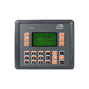
ICP DAS VP-2117 - *Discontinued* - ISaGRAF version of VP-2111
by ICP DAS
|
|
|
|
ISaGRAF PAC with display and keypad (MiniOS7 inside). IP65 Compliant Front Panel.
|
|
|
Features
ViewPAC series VP-2117 is the ISaGRAF PAC with graphic display and keypad. It is equipped with an 80186 CPU (16-bit and 80 MHz) running a MiniOS7 operating system, 3 I/O slots, a STN LCD, a rubber keypad and various connectivity including Ethernet and RS-232/485.
The ViewPAC - VP-2117 supports ISaGRAF Ver. 3 Workbench:
- IEC 61131-3 Standard Open PLC Programming Languages (LD, FBD, SFC, ST, IL, FC) + Flow Chart (FC)
- Auto-Scan I/O
- On-Line Debugging/Control/Monitoring, Off-Line Simulation
- Simple Graphic HMI
Its operating system, MiniOS7, can boot up in a very short time (0.4 ~ 0.8 seconds). It has a built-in hardware diagnostic function, and supports the full range of functions required to access all high profile I-8K and I-87K series I/O modules, such as DI, DO, DI/DO, AI, AO, Counter/Frequency, motion control modules, etc. Users can also choose RS-485 Remote I/O modules (I-7000 series) or expansion units (RU-87Pn or I-87Kn) plugged with high profile I-87K serial I/O modules.
Compared with traditional HMI + PLC solutions, ViewPAC reduces overall system cost, space and gives you all the best features of HMIs and PLCs.
Software Features
- MiniOS7 Embedded Operating System (DOS-like)
- ISaGRAF Ver.3 SoftLogic Inside
- Support IEC 61131-3 Standard
- Supports Graphic and Keypad functions
- Accepts max. 64 KB ISaGRAF code size
Hardware Features
- 80186 CPU (16-bit & 80 MHz)
- 768 KB SRAM & 512 KB Flash
- IP65 Compliant Front Panel
- Rubber Keypad
- STN LCD with English and Chinese Fonts
- 3 I/O Expansion Slots (support High Profile I/O Modules)
- 64 MB NAND Flash for Data Storage
- 10/100M Ethernet Port
- 3 Serial Ports (RS-232, RS-485)
Applications
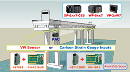
Stress Monitoring Application of Constructions
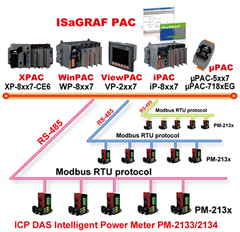
ISaGRAF PAC connects the Smart Meter
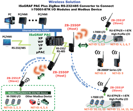
ZigBee Wireless Solution
| Integrate with CAN/CANopen Devices and Sensors |
SMS: Short Message Service |
| Send Email with One Attached File |
Motion Control |
| An Easy Way to Program the Fast FRnet Remote I/O Modules |
Data Recorder and Data Logger |
| Data Acquisition Auto-Report System |
Data Exchange: Fbus or Ebus |
| Modbus RTU/TCP Slave Ports |
Detect Hot-Swap I-87K (High Profile) I/O Status |
| Modbus RTU/ASCII Master Ports |
VIP Communication Security |
| Remote I/O Modules and Expansion module/board |
|
|
| Models |
VP-2117 |
VP-2117-TC |
| System Software |
|
| OS |
MiniOS7 |
| Development Software |
|
| ISaGRAF Software |
ISaGRAF Version 3 : IEC 61131-3 standard. Languages: LD, ST, FBD, SFC, IL & FC |
| Max. Code Size |
Accepts max. 64 KB ISaGRAF code size (Appli.x8m must < 64 KB) |
| Power Supply |
|
| Input Range |
+10 ~ +30 VDC |
| Isolated |
1 kV |
| Capacity |
3 A, 5 V supply to I/O expansion slots |
| Power Consumption |
6 W (0.25 A @ 24 VDC) |
| General Environment |
|
| Temperature |
Operating: -15 ~ +55 °C,
Storage : -30 ~ +80 °C |
| Humidity |
10 ~ 90 % RH (non-condensing) |
| System |
|
| CPU |
80186 (80 MHz and 16-bit) or compatible |
| Watchdog Timers |
Yes (0.8 second) |
| RTC (Real Time Clock) |
Provide second, minute, hour, date, day of week, month, year |
| SRAM |
768 KB |
| Dual Battery Backup SRAM |
512 KB (for 5 years data retention while power off) |
| FLASH |
512 KB (100,000 erase/write cycles) |
| FLASH Disk |
64 MB NAND Flash (100,000 erase/write cycles) |
| NVRAM |
31 bytes (battery backup, data valid up to 5 year) |
| EEPROM |
16 KB, Data retention: 40 years. 1,000,000 erase/write cycles |
| Serial Number |
Yes,64-bit hardware unique serial number |
| Communication Interface |
| Ethernet |
RJ-45*1, 10/100 Base-TX, (Auto-negotiating, LED indicators), program download port. |
| COM0 |
Internal communication with the I-87K High Profile modules in slot 0 ~ 2 |
| COM1 |
RS-232: TxD, RxD, GND, Speed: 115200 bps max. Program downloads port. |
| COM2 |
RS-485 (D+, D- ); Speed: 115200 bps max. ; 2500 VDC isolated |
| COM3 |
RS-232/RS-485
RS-232:TxD,RxD,GND,CTS,RTS ; RS-485: DATA+,DATA-,
Speed: 115200 bps max. Program downloads port. |
| I/O Expansion Slots |
|
| Slot Number |
VP-2117: 3 slots (slot 0 ~ slot 2) |
| * Accept only High Profile I-8K Parallel & High Profile I-87K Serial I/O boards |
| Hot Swap |
* For High Profile I-87K I/O modules in slot 0 ~ 2 only |
| Data Bus |
8/16 Bits |
| Address Bus Range |
2 K for each slot |
| MMI (Man Machine Interface) |
| LCD Type and Size |
STN, 128x64 Dot Matrix LCD |
| Text Font |
English + Simplified Chinese |
English + Traditional Chinese |
| Display Mode |
Text + Graphics |
| Rubber Keypad |
24 keys |
| Buzzer |
Yes |
| LED Indicators |
3 Dual-Color LEDs (PWR, RUN, LAN1, L1, L2, L3; L1 ~ L3 for User Programmable) |
| Mechanical |
|
| Dimensions (W x L x H) |
182 mm x 158 mm x 125 mm |
| Ingress Protection |
Front panel: IP65 |
| Motion |
|
| Motion Control |
one I-8091W (2-axis) or two I-8091W (4-axis) to do motion control. Ethernet communication is also available when doing motion control. |
| PWM Output |
|
| High Speed PWM Module |
I-8088W:
8-ch PWM outputs, software support 1 Hz ~ 100 KHz (non-continuous), duty: 0.1 ~ 99.9% |
| DO Module as PWM |
8-ch. max. 500 Hz max. For Off=2 & On=2 ms . Output square wave: Off: 2 ~ 32766 ms, On: 2 ~ 32766 ms.
Optional DO Boards: I-8037W, 8041W, 8041AW, 8042W, 8050W, 8054W, 8055W, 8056W, 8057W, 8060W, 8063W, 8064W, 8068W, 8069W. (Relay Output boards cannot generate fast square wave) |
| Counter, Encoder, Frequency |
| Parallel DI Counter |
8-ch. max. For 1 controller. Counter val: 32-bit. 500 Hz max. Min. ON & OFF width must > 2 ms. Optional DI boards: I-8040W, 8040PW, 8042W, 8046W, 8048W, 8050W, 8051W, 8052W, 8053W, 8053PW, 8054W, 8055W, 8058W, 8063W. |
| Serial DI Counter |
Counter input: 100 Hz max. Counter value: 0 ~ 65535 (16-bit)
Optional serial I-87K DI boards: I-87040W, 87046W, 87051W, 87052W, 87053W, 87053W-A5, 87054W, 87055W, 87058W, 87059W, 87063W. |
| Remote DI Counter |
All remote I-7000 & I-87K DI modules support counters. 100 Hz max. value: 0 ~ 65535 |
| High Speed Counter |
I-87082W: 100 kHz max. 32 bit;
I-8084W: 250 kHz max. 32 bit |
| Encoder |
I-8093W: 3-axis Encoder Module, max. 1M Hz for quadrant input mode, max. 4M Hz for
pulse/direction and cw/ccw input mode.
I-8084W: 250 kHz max., 4-ch encoder, can be pulse/direction, or Up/Down or A/B phase
(Quad. mode); Not support Encoder Z-index. |
| Frequency |
I-87082W: 2-ch, 1 Hz ~ 100 kHz;
I-8084W: 8-ch, 1 Hz ~ 250 kHz; |
| Protocols |
|
Modbus RTU/ASCII Master
Protocol |
Up to 2 COM Ports (COM1 ~ 3 and COM5 if multi-serial port boards are plugged in)can support Modbus RTU Master or ASCII Master protocol to connect to other Modbus Slave devices, 2 ports support up to 128 Modbus_xxx function blocks (same type). |
Modbus RTU Slave
Protocol |
Up to 2 COM Ports, COM1 and one of (COM2, COM3) can support Modbus RTU Slave protocol for connecting ISaGRAF, PC/HMI/OPC Server & MMI panels. |
Modbus TCP/IP Slave
Protocol |
Support Modbus TCP/IP Slave protocol for connecting ISaGRAF & PC/HMI. (Max. 6 connections) |
| Remote I/O |
One of COM2, 3 supports I-7000 I/O modules & (I-87K base or RU-87P1/2/4/8) + I-87K High Profile I/O cards as Remote I/O. Max. 64 Remote I/O module for one controller |
| Fbus |
Built-in COM3 Port to exchange data between ICP DAS's ISaGRAF PACs. |
| Ebus |
To exchange data between ICP DAS's ISaGRAF Ethernet PACs via Ethernet port. |
SMS:
Short Message Service |
One of COM3 or (COM5 in multi serial port board) can link to a GSM modem to support SMS. User can request data/control the controller by cellular phone. The controller can also send data & alarms to user's cellular phone. Optional GSM/GPRS modem: GTM-201-RS232 (850/900/1800/1900 GSM/GPRS External Modem) |
| User-defined Protocol |
User can write his own protocol applied at COM1 ~ COM3 (& COM5 ~ COM16 if multi-serial port boards are plugged) by serial communication function blocks. |
| CAN/CANopen |
Up to 3 COM Port. User can use its COM1, 3, or (COM5 ~ COM12, resides at the I-8112iW/8114W/
8114iW RS-232 expansion board) to connect one I-7530 (RS-232 to CAN converter) to support CAN/CANopen devices and sensors. One VP-2117 supports max. 3 RS-232 Ports to connect max. 3
I-7530. |
| FRnet I/O |
Support Max. 3 I-8172W FRnet Master cards to connect FRnet I/O modules. (Max. 768-ch. DI + 768-ch. DO) |
| Sending E-mail |
Actively or passively sending E-mail via Ethernet port through internet. Max.10 receivers for each sending and can send E-mail with an attached file. (Max. file size is about 488 KB) |
Demo Files
| Project Name |
Description |
I/O Boards Or Complex Equipment Used |
| Demo_01 |
To output at a time interval: SYSDAT_R, SYSDAT_W, SYSTIM_R, SYSTIM_W (ST+QLD) |
|
| Demo_02 |
To do something at some sec later when an event happens |
I-8055 |
| Demo_03 |
Convert float value to string, using real_str & rea_str2 |
|
| Demo_04 |
PID control, refer to CD:napdosisgrafwinconenglish_manu"PID_AL.. |
|
| Demo_05 |
Store & backup boolean & long integer value To/From EEPROM |
|
| Demo_06 |
Retain variable by Retain_b, Retain_N, Retain_f, Retain_t |
|
| Demo_07 |
Receive String coming from remote PC or controller via UDP/IP |
udp_ip |
| Demo_08 |
Using "com_MRTU" to disable/enable Modbus RTU slave port, |
|
| Demo_09 |
PWM I/O demo. (Pulse Width Modulation), minimum scale is 1ms for VP-2xx7 |
I-8055 |
| Demo_10 |
Send Time String to COM3:RS232 every second by using COMOPEN, COMSTR_W |
|
| Demo_11 |
Send string to COM2 when alarm 1 to 8 happens, slot 1: i8077 |
Slot 1: I-8077 |
| Demo_12 |
Read Real Val from Modbus RTU device |
mbus |
| Demo_13 |
Write Real Val to Modbus RTU device |
mbus |
| Demo_14 |
Using Modbus function code 6 to write 16 bits |
mbus |
| Demo_15 |
COM3 connecting 1: M7053D + 2: M7045D (MBRTU format, baud=9600) |
mbus
M-7053D
M-7045D
|
| Demo_16 |
COM3 connecting 1: M-7053D to get D/I counter value (MBRTU format, baud=9600) |
mbus
M-7053D |
| Demo_17 |
COM3 connecting 1: M7017R + 2: M7024 (MBRTU format, baud=9600) |
mbus
M-7053D
M-7024 |
| Demo_18 |
COM3 connecting 1: M7017RC , Current input, +/- 20 mA, 4-20 mA (Modbus format) |
mbus
M-7017RC |
| Demo_19 |
COM3 connecting 1: M-7019R (set as T/C K-type input) (MBRTU format, baud=9600) |
mbus
M-7019R |
| Demo_20 |
COM3 connecting 1: M7080 (MBRTU format, baud=9600) |
mbus
M-7080 |
| Demo_21 |
test Msg_F. i8xx7 since 3.19. i7188EG/XG since 2.17 & 2.15. W-8xx7 since 3.36 |
|
| Demo_22 |
test Msg_N. i8xx7 since 3.19. i7188EG/XG since 2.17 & 2.15. W-8xx7 since 3.36 |
|
| Demo_23 |
Auto-report data to PC via UDP.Controller=10.0.0.103, PC=10.0.0.91 |
udp_ip
bus7000b |
| Demo_24 |
Send email via Ethernet port. (To one receiver without attached file) |
|
| Demo_25 |
VP-2xx7 : Record 1~4 Ch. voltage every 50ms and draw trend curve by M.S.Excel |
I-8024
I-8017h
s256_512
Push4Key,
Show3Led |
| Demo_26 |
Send UDP Str to PC when alarm trigered(variable array), Time_Gap is 1 sec |
I-8077
udp_ip |
| Demo_26a |
Send UDP Str to PC 3 sec later when alarm (variable array), Time_Gap is 250ms |
I-8077
udp_ip |
| Demo_27 |
For VP-2117. Send email to a receiver with an attached file |
|
| Demo_28 |
Get driver version of VP-2xx7 |
|
| Demo_29 |
Display a string to VP2000 starting at (X_, Y_) on the LCD |
lcd_init |
| Demo_30 |
Display a Traditional Chinese to VP2000-TC starting at (X_, Y_) on the LCD |
lcd_init |
|
|