|
|
|
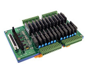
ICP DAS DB-24SSR - 24-channel Solid State Relay Output Board with 1.5 meter 50-pin flat-cable
by ICP DAS
|
|
|
|
24-channel Solid State Relay Output Board. Includes CA-3710(37-pin D-sub Cable)
|
|
|
The DB-24SSR/DB-24SSRDC includes 24 normally open, or form A, solid-state relays The board interface to filed logic signals, eliminating ground-loop problems and isolating the host computer from damaging voltages. The user can use the DB-24SSR/DB-24SSRDC to switch high voltage load, up to 240 VAC/50 VDC and up to 4 A. The relay is energized by applying a 5-voltage signal to the appropriate relay channel on the 50-pin header or 37-pin D-sub connector. Twenty-four enunciator LEDs, one for each relay, light when their associated relay is activated. Because there is a D-sub 37-pin connector on the board, the user may use it to interface to any TTL output board. In other words, the user may use it as a general purpose solid state relay output board.
- 24 optically isolated digital output channels
- 24 form A solid-state relays
- Switch up to 4 A at 250 VAC/50 VDC for DB-24SSR/DB-24SSRDC
- One OPTO-22 Compatible Connector and one 37-pin D-sub connector and one 20-pin connector
- Connects directly to OPTO-22 compatible board or any 722,724 series board
- LED’s indicated relay status
- Screw terminals for easy field wiring
| |
DB-24SSR |
DB-24SSRDC |
| Solid State Relay |
AC |
DC |
| Load Voltage |
50~250 VAC |
3~50 VDC |
| Maxi. Load Current |
4 A |
| Repetitive Peak OFF Voltage |
600 V |
1 mA |
| Max. “ON-state “ Voltage Drop |
1.5 V |
1.2 V |
| Surge Current |
50 A |
10 A |
| Maxi. “OFF-State” Leakage Current |
5 mA |
1 μA |
| Mini. Load Current |
20 mA |
1 mA |
| Breakdown Voltage |
2,500 V (Between Input & Output) |
| Insulation resistance. i. |
100,000,000 Ω(min.) |
| Operate time , 1/2 cycle of voltage sine wave |
1 ms (max.) |
0.5 ms (max.) |
| Zero Crossing |
Yes |
| Snubber Circuit |
Yes |
| Power Consumption |
0.4 A @ +5 V (max.) |
| Operation Temperature |
0 ~ 60 °C |
| Storage Temperature |
-20 °C ~ 70 °C |
| Humidity |
5% ~ 90% RH, non-condensing |
| Dimension |
130 mm x 220 mm |
|
|
|
|