|
|
|
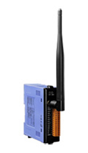
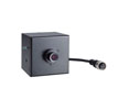
ICP DAS ZT-2026 - 4 Channel Analog Inputs, 2 Channel Analog Outputs, 2 Digital Outputs
by ICP DAS
|
|
|
|
Zigbee Wireless 4-channel Voltage Input (Current Input) Analog Input, 2-channel Voltage Output, 2-channel Digital Input and 2-channel Digital Output Zigbee Data Acquisition Module. Supports DCON and Modbus RTU Protocols, and has operating temperatures from -25°C ~ +75°C (-13°F ~ 167°F).
|
|
|
The ZT-2026 is a wireless ZigBee module that offers 4 differential analog input channels, 2 analog output channels, 2 digital input channels and 2 digital output channels and provides a programmable analog input and output range. Each analog input channel can be configured to an individual range and each has 240 Vrms overvoltage protection. There are also options for a power-on value and a safe value. Users can easily confi gure the module address, protocol, checksum, ZT-PID, ZT-channel and type code settings using a combination of rotary and DIP switches.
- ISM 2.4 GHz Operating Frequency
- Fully Compliant with 2.4G /ZigBee Specifications
- Wireless Transmission Range up to 700 m
- GUI Configuration Software (Windows Version)
- 4 AI, 2 AO, 2 DI and 2 DO Channels
- Individual Channel Confi guration
- Overvoltage Protection is up to 240 Vrms
- Surge and ESD Protection
- DIN-Rail Mountable
Building Automation, Factory Automation, Machine Automation, Remote Maintenance, Remote Diagnosis, Testing Equipment.

| Communication Interface |
| Wireless Standards |
ZigBee 2007 Pro |
| Transmission Power |
11 dBm(FCC Certificated) ( Max 19 dBm) |
| 2.4 GHz Antenna |
5 dBi Omni directional |
| Transmission Range (LoS) |
700 m (Typical) |
| Certification |
CE/FCC, FCC ID |
| Max. Slaves in a ZigBee Network |
255 |
| ZB-100R/ZB-100T Support |
- |
| Protocols |
Supports DCON and Modbus RTU Protocols |
| Hot Swap |
Rotary and DIP switch |
| LED Indicators |
| Power |
1 LED, red |
| ZigBee Communication |
1 LED, green |
| Isolation |
| Intra-module Isolated, Field-to-Logic |
2500 VDC (for AI, AO, DI and DO) |
| EMS Protection |
| ESD (IEC 61000-4-2) |
4 kV Contact for Power Line, Communication Line and each Channel, 8 kV Air for Random Point |
| EFT (IEC 61000-4-4) |
4 kV for Power Line |
| Power |
| Input Voltage Range |
+10 VDC ~ +30 VDC (Reverse Polarity Protection) |
| Power Consumption |
2.1 W Max. |
| Mechanical |
| Flammability |
Fire Retardant Materials (UL94-V0 Level) |
| Dimensions (W x L x H) |
33 mm x 87 mm x 107 mm |
| Installation |
DIN-Rail |
| Environment |
| Operating Temperature |
-25 °C ~ +75 °C |
| Storage Temperature |
-30 °C ~ +80 °C |
| Relative Humidity |
10 ~ 90% RH, Non-condensing |
I/O Specifications
| Analog Input |
| Input Channels |
4 Differential |
| Input Types |
+/-10 V, +/-5 V, +/-1 V, +/-500 mV, +/-150 mV or -20 mA ~ +20 mA (Requires Optional External 125 Ω Resistor) |
| Resolution |
16-bit |
| Sampling Rate |
10 Samples/Second (Total) |
| Accuracy |
+/-0.1% of FSR |
| -3dB Bandwidth |
15.7 Hz |
| Zero Drift |
+/-20 μV/°C |
| Span Drift |
+/-25 ppm/°C |
| Common Mode Rejectio |
86 dB |
| Normal Mode Rejection |
100 dB |
| Input Impedance |
>2 MΩ |
| Overvoltage Protection |
240 Vrms |
| Individual Channel Confi guration |
Yes |
| Analog Output |
| Output Channels |
2 |
| Output Types |
+/-10 VDC, +/-5 VDC, 0 ~ 10 VDC or 0 ~ 5 VDC |
| Resolution |
12-bit |
| Accuracy |
+/-0.1% of FSR |
| Zero Drift |
+/-30 μV/°C |
| Span Drift |
+/-25 ppm/°C |
| Programmable Output Slope |
0.0625 ~ 512 V/Second |
| Voltage Capability |
20 mA @ 10 V |
| Power-on and Safe Value |
Yes |
| Digital Input |
| Input Channels |
2 (Sink) |
| On Voltage Level |
3.5 VDC ~ 50 VDC |
| Off Voltage Level |
1 VDC Max. |
| Input Impedance |
10 KΩ |
| Event Counters |
Channels : 2 |
| Max. Count: 16-bit (65535) |
| Max. Input Frequency: 50 Hz |
| Min. Pulse Width: 10 ms |
| Digital Output |
| Output Channels |
2 (Sink) |
| Output Types |
Isolated Open Collector |
| Max. Load Current |
700 mA/channel |
| Load Voltage |
+5 VDC ~ +50 VDC |
| Short Circuit Protection |
Yes |
|
|
|
|